3D Printer – now better

As I mentioned in the last blog post, I printed a new z-endstop for the printer to replace the one zip-tied in place. The problem with the zip tie stop was the zip tie was on a smooth rod, and it would move if bumped by the carriage.

The first one I printed looked pretty nice; it mounted on one z-axis motor and was designed to hold the microswitch up to contact a printed adjustment piece. The problem with this type was first the mount holes were totally wrong for the style of microswitch I had (too close) and the triangular shape of the holder prevented proper holes from being drilled. The adjuster also would not fit on my x axis motor, so the whole thing was a dud.

I kept looking and finally found a printable small triangular mount that was easy to print, and captures the microswitch perfectly. It takes up almost no room. I had to print this one using a cobbled together solution as I’d removed the zip-tied endstop trying to get the first printed one to work. The printing was not great (the holes were not centered properly) but I was able to drill it and once installed it works perfectly.

Since then I’ve printed a few things, and had a few failures due to my newness at 3d printing, but it’s all good and fun again.

3D Printer – It’s dead, Jim… no wait! IT’S ALIVE!!! (and a lesson)

Yea, I know. Really, really cheezy title. Tough.

Last week I went to make a print for my underwater video light – a quick disconnect ball mount so I can leave the ball mount permanently attached to the video light no matter what housing I use. It looked pretty straightforward, and I started to print…

… only to find it was pooping it’s thread from about 5mm instead of onto the bed. I checked and confirmed the height was off, so corrected it. It did it again! I tested the x-axis extruder height, and it was also off level. This was very strange as nothing had changed, but as I was checking I discovered the z axis was moving when I touched it. It is NOT supposed to do that.

More checking confirmed the bad news – one of the nuts that is part of the z axis was totally stripped. You could take the threaded rod and zip it back and forth holding the nut. The other nut was OK, but for now the printer was down.

A detailed analysis plus a bit of an “aha” moment involving the same threaded rod and the video light made me realize the so-called 5mm threaded rod was actually a 10-32 imperial thread. It was not metric at all. I have 10-32 nuts, bought as part of the video light project, and they fit perfectly on the threaded rod. More interestingly, the 5mm nuts showed significant “lash” on the rod while the 10-32 nuts showed almost none.

The only problem was the 10-32 nuts were too large to mount on the printer. I tried epoxy, but it just peeled off the PLA mount once cured. All the fancy stores were closed Saturday, including one that was supposed to be open but could not bother to post that on the website or make an answering machine message, so I was out of luck until today.

This morning I went to Fastenal in Nanaimo, looking for “threaded rivets” a.k.a. rivet nuts. These are marvelous threaded tubes about .5 in long by whatever thread you want. They would solve the problem perfectly. Unfortunately, they were out of stock and it would be a week for more. However, they did have true 5mm stainless threaded rod and stainless 5mm nuts. I bought both, came home and cut the rod to length and installed it. With the new nuts, it was back to a working printer in a matter of about an hour.

Once rebuild, I had to level the x axis again. The height is controlled by the two z axis threaded rods, and though you can get really close by evening the nuts before you assemble it, it’s best to fine tune with a strip of paper and the extruder.

The first print was again the 20mm cube, as that’s a really good test of the printer and allows me to verify all dimensions. It turned out the z face was high – 20.05mm and not 20mm, so I grabbed the internet and checked thread pitches. It turns out they are most certainly NOT the same. 10-32 is 32 tpi (thread per inch), or 0.03125 / inch. Metric 5mm is usually 0.8mm pitch, which is 0.03150. It seems so close, but when dealing with 0.1 mm it’s not close enough. The 0.8mm pitch is just a tad coarser – equivalent to 31.75tpi. I adjusted the firmware print constant to account for the difference, and the second 20mm cube was exactly 20mm as it should be.

Now I’m printing a new z-endstop for the printer. The current z endstop is just zip tied in place, and it would move while I was leveling the x axis. This is not good, so I found some printable ones and will see what I can devise.

At least the printer is again functional, which is a great relief to me.

More 3D Printing

I’m reflecting on the 3D printer and how it’s been working for me, and overall I’m very happy. For something I build from plans but with a lot of my own design, it’s working very well.

Some notes so far:

  • I used a caliper to measure my cubes. They are, in fact, exactly 20mm on every face. They did not shrink. That’s great news.
  • slic3r is a great program. In addition to letting you preview layers, it has scaling features. Using those I scaled the 20mm cube by 200% today and thus printed a perfect 40mm cube (confirmed by the calipers).
  • The blue tape is an excellent bed for PLA prints
  • There are a lot of available things to print on the internet, but now it’s time to learn blender and make some of my own. There are things I want to print that no-one else has designed yet, so now it’s my turn. 🙂

Today I’m printing a lens gear for the Canon DLSR. I doubt it will fit in the underwater housing (or interlock with the control wheel if it does, but it’s a start and I can then work with designs to create my own focus and/or zoom gears down the road.

More 3D Printing Fun

Today I was able to get back to the 3D printer after several days dealing with a major server crash.

After talking to my AU collaborator, I wanted to try extruding at the recommended temperature of 185C instead of 210C that I’d been using. One problem with hotter extruding is that the tip tends to ‘leak’ filament at idle.

My friend also recommended a colder bed, saying he used 30C instead of 60C.

I also configured an old APC UPS due to a power outage yesterday due to wind so that the printer wouldn’t die during a print if the power went out again. Although we have a generator, it takes 1 min to detect and respond to an outage, and a UPS saves the day during this interval.

I powered up the printer and used pronterface on my PC to set the extruder temperature to 185C. Once at temp I test extruded several cm of thread and it worked perfectly.

The last modification I made to the printer was to replace the tape on the aluminum bed with blue painter’s tape I bought earlier in the week. I figured this tape had a nicer pattern which might give better grip to the print.

I started the latest version of slic3r on my PC and set the new extruder and bed temperature as defaults, then loaded the 20mm cube and exported new gcode. I copied the gcode to the printer SD card, then inserted it into the printer and started the print. It was fast!!! The cube printed in 15 min, which is about twice as fast as the first time. I used a honeycomb fill pattern, which contributed to the speed, but it was still very fast. The new cube was identical to the first cube except for the fill pattern.

Finally, I found a model of a moai (Easter Island statue) on the web, and loaded into slic3r. It was a bit big, so I scaled it down by 50%, created the gcode file and copied that to the printer SD card.

It printed in just over 2 hours, and although there were issues with the filament not coming off the spool smoothly, there were no problems with the print. It’s awesome! The blue tape worked perfectly; I needed to really tug to remove the finished print.

I’ve attached photos of the moai printing as well as the final print. I also added some photos of the filament on the reel showing how it seems to be poorly wound at the factory. I’m not sure what I’ll do about that. Probably I’ll just live with it for this spool and buy a different brand from now on.


Moai printing   


Finished moai

. 


Filament problems   

3D Printer Build (Prussia I3) – Jan 2016 to July 2017

I can’t believe that is’ been May since I last posted, but worse – I cannot believe I never posted anything about my 3D printer build. That’s terrible!

Well, to correct the omission, onward.

In January 2016 I started building a 3d printer with the encouragement from a colleague at Athabasca University. He had built one and thought I’d love doing it as well. He was an immense help, first giving me a detailed list of what to purchase from which ebay vendor, then actually printing the key plastic parts on his printer and sending them to me.

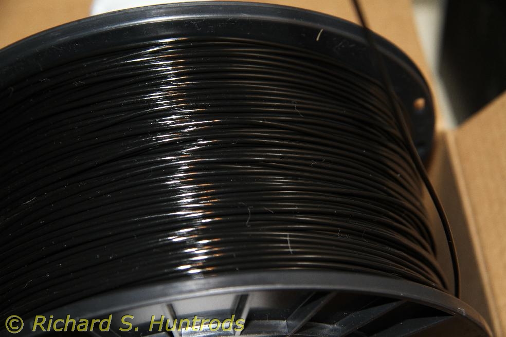
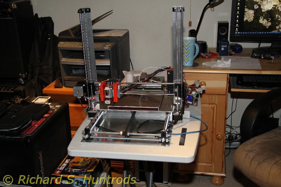
The idea was to custom build a Prussia I3 printer rather than buy a kit. Kits were/are costly, and don’t always use the best parts. By purchasing exactly what you want, you can customize the build as well as optimize the quality. In the end I bought about $350 worth of stuff from ebay, including rods, bearings, heated bed, stepper motors, extruder and all the electronics. A note about the electronics – the Prussia I3 can use many boards, but we used the RAMPS 1.4 which includes the arduino mega and an LCD control panel. The RAMPS has controllers for all the stepper motors as well as the extruder and heated bed. It runs off a slightly modified ATX power supply as it needs 12V at 25A.

I also bought  other parts locally, such as threaded rod, nuts and washers, as well as some aluminum plate for the frame and beds. Here I ended up spending about $225, so my total build cost was $575 (Canadian funds) including shipping and taxes.

The hard part initially was waiting. Buying this stuff off Ebay means Hong Kong, which in turn means 2 weeks to 1+ months delivery wait times. It gets pretty difficult to keep enthused while you check the post each day.

Finally in Feb or so most of the parts were in, and I could start. There are a lot of really good build videos and instructions on the internet, so I started with those.

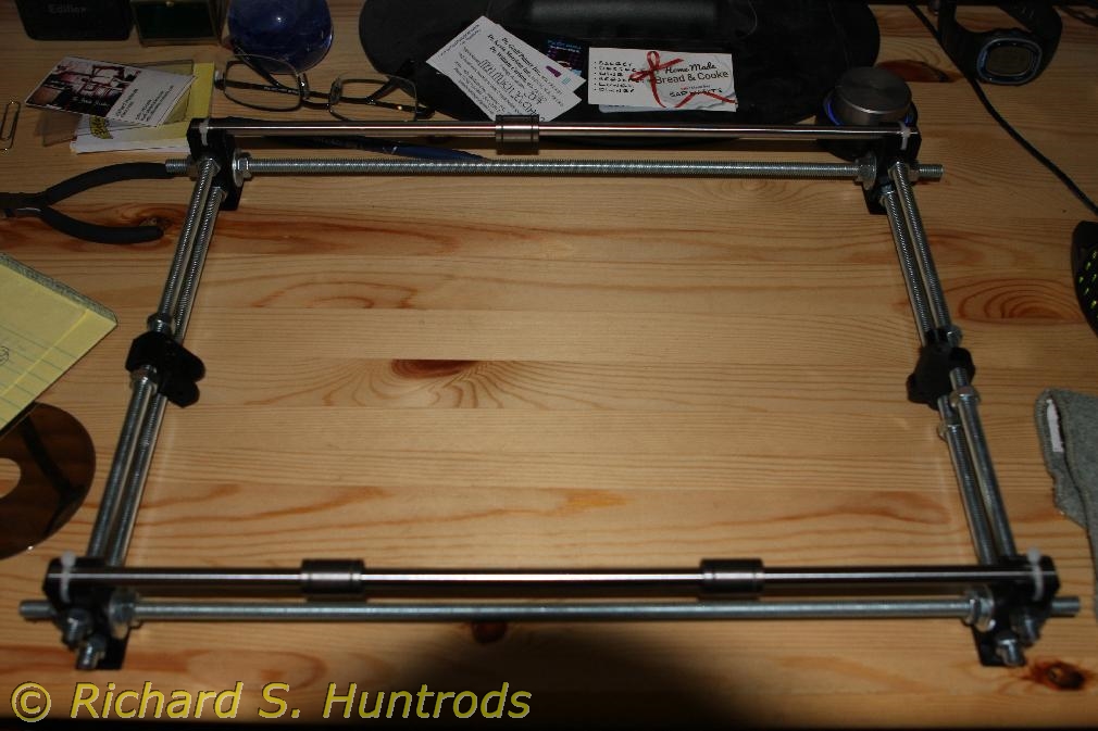
By March I had the basic Y axis and X asis frames build, and there I stalled. My colleague used wood for his base and support structures, but I didn’t have the right wood and just could not get enthused about wood for this build. So I put it all away in a box for safekeeping, and  there it sat until late May of 2017.

Then I had an epiphany. I would build the frame from aluminum plate, as it’s easy to work with, relatively inexpensive and easy to get and have cut. I checked the built y axis against a large sheet of cut aluminum plate, and it fit perfectly. From there it began anew.

First I made sure the Y axis was true, then glued the feet to the aluminum plate with epoxy. Once that had cured, I started to design the vertical support system for the X and Z axes. Gradually it came together. Of course, the design/test/correct process means most of the holes become slots, but that’s not a big problem.

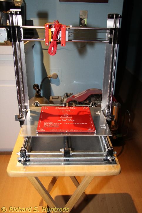
Once I got going, things really progressed quickly. The biggest problem became a lack of M3 bolts in various sizes. I’d originally bought a few specific sizes from an Ontario mail order outfit, but they were pricey and selection poor. Finally in June 2017 I bit the bullet and ordered a 440 variety pack from Hong Kong, figuring a month wait. To my surprise, it came in a week and I was back in business with even more renewed vigor.

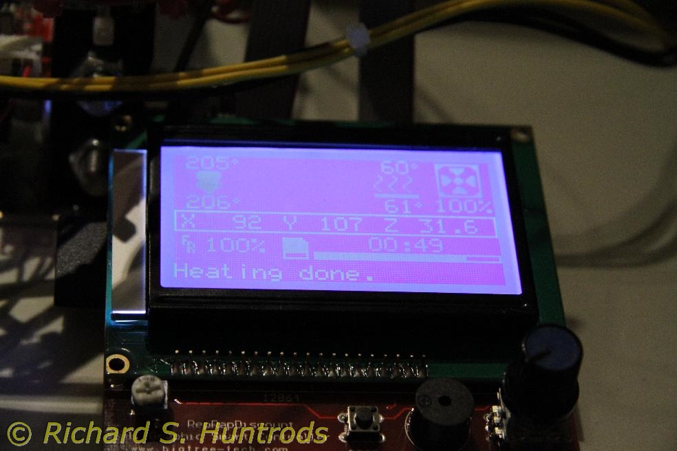
By the fist week in July I had the printer complete, and started testing. There I hit some major snags. All the build instructions said “the kit comes with firmware loaded”. Well, I didn’t use a kit, so there was no firmware. Worse, my colleague from AU no longer worked there, and it took some time to reconnect. Finally I did, and with a few tips from him I was able to find the arduino software that compiles to the firmware that drives the printer.

This highlighted a further problem: the firmware has about a zillion parameters that must be set for your particular printer. Some aren’t critical, but others (like stepper motor settings) are essential. Fortunately the default parameters are pretty close for most things, and there are ample comments and options to get things up and running without too much bother.

Then there’s the ancillary software. To build a model, the printer needs instructions. The process is simple in theory. You take a 3d model and load it into a ‘slicer’ program which creates the actual instructions to drive the printer. It’s all very cool and open source, with the ‘gcode’ file being completely human readable. You can even manually tweak the file if you want. The problem yet again is the slicer program has   dozens of options, most of them critical for a good print.

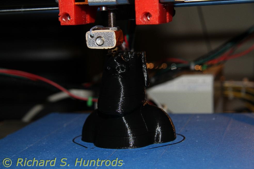
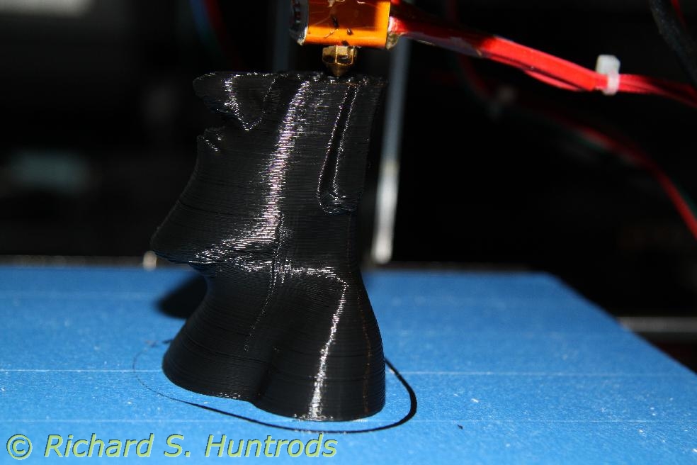
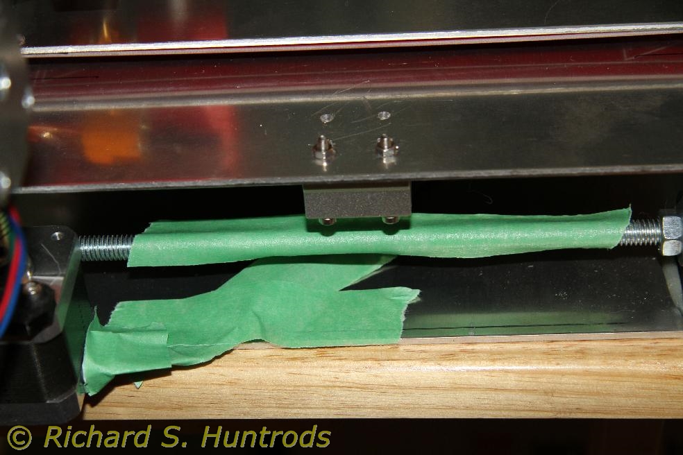
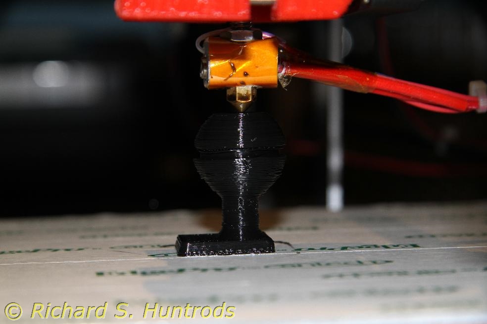
Ultimately I got most things running by July 10, with the exception of the extruder. No matter what, it just created puddles of goo that it would then plow through while trying to print. After much internet searching, I found one document that discussed “extruder calibration”. Now I’d already calibrated the X, Y and Z stepper movement, which turned out to be perfectly aligned with the firmware default stepper rates. Of course I figured the supplied default would be correct for the extruder as well. However, puddles of goo said otherwise, so I calibrated the extruder. You simply make a mark on the filament, extrude a set amount and see if the actual movement matches the desired movement. To my surprise, I was running 5x what I wanted. Fortunately, with all those parameters in the firmware source, it was quick work to enter a corrected extruder parameter, and another test showed that I was now spot on.

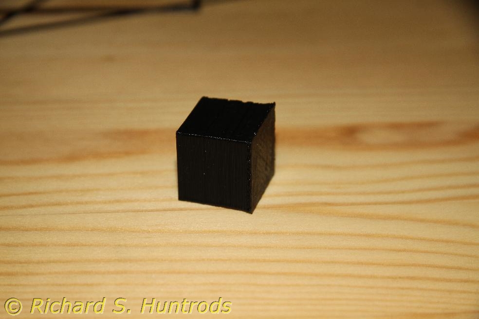
With that, I printed my first 3d object on July 10, 2017 – a 20mm cube using PLA filament. When cooled, it was 19mm on every side, straight and true, so I am very happy with the operation of my 3d printer.

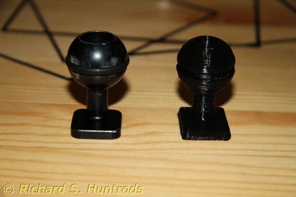
Later that night I printed a 1inch ball mount for my underwater video light, and it’s also turned out perfect.

Here’s a link to a video of the printer creating the cube: https://youtu.be/h1DfgUolt5A