More 3D Printed goodies

A week ago the ancient electric pencil sharpener died. The motor could be heard spinning when  a pencil was inserted, but no sharpening action. I took it apart to find the large gear that drives the sharpening mechanism was broken in two pieces. As I shook it out, it broke again. Time for a new unit? Not with a 3D Printer! Before I gave up on this item, I would try and print a replacement gear.

Designing gears is not fun, but the on-line CAD program Tinkercad had a community supplied gear builder. I took measurements from the broken gear, counted the teeth (70) and designed a new one. My first print wasn’t correct. The broken gear did not reveal the drive slot was only partially into the gear, with a round shaft for the rest. Once I had one new gear with the slot all through it was easy to see what needed to be done. The next gear fit well and worked. It’s noisy, but it works.


The next challenge was designing an optical connector for my underwater camera housing. The very expensive part from the manufacturer (double any equivalent price) screws onto an optical fitting on the housing. The bare cable has an optical end, but must be mechanically connected to the strobe and housing. On the strobe it’s a simple hole, but I needed something similar on the housing. Again using Tinkercad, I was able to design a simple connector. It took a few tries to get the sizes correct as things must be tight but still fit. After 5 tries I had a good fit. Now to take it to the water for a test dive.  The optical port is shown mounted on the housing on the upper center left.

FLSUN delta printer update for 2017-10-24

Yesterday the new aluminum extruder came from amazon.ca for my delta printer. It was nicely packaged and although the instructions could have been better (b&w photos aren’t great for assembly), they were adequate.

I removed the original plastic-parts extruder and installed the new extruder. It was immediately obvious the mechanism is much better than the original. The toothed wheel is a much finer tooth count, and the idler wheel with notch is much smoother. The spring tension is not adjustable either from close examination nor from the assembly photos, but seems to work in an excellent fashion.

The only hiccup was when I tried to test the calibration. No matter what, I could not get it to extrude. Finally, after much frustration, I realized the two settings in pronterface are not extrude lenght / reverse length, but rather settings for 1.extrude/reverse length and 2. extrude/reverse SPEED. Setting it from the default of 10mm/min to 120mm/min (2mm/sec) was all it took to see some action. Unfortunately the operation was now reversed due to placement of the idler compared to the original extruder.

Fortunately there’s a setting in the configuration.h file for stepper direction which includes the extruder stepper. Flipping the binary option caused the extruder to properly extrude/reverse. Due to the finer gear spacing, asking for 1cm gave 1.4cm. It’s a quick parameter change to fix that and confirm requesting 1cm now gives 1cm extrusion (and retraction).

Finally, I reconnected the filament and tube to the hot end, burning myself severely in the process (2nd degree on a finger which slipped). Once connected I made a test print of the benchy (boat). The first layer is still off, but now at least I can make adjustments knowing the extruder is functioning properly.

Final lesson learned: 185C is VERY, VERY hot. It will cause an instant 2nd degree burn as I found out to my distress. Fortunately immediate cold water followed by ice for 2 hours has reduced the damage significantly.

3D Delta Printer Update

I was not happy with the first prints out of the delta printer. In spite of upgrading the firmware from Marlin 1.0 to Marlin 1.1.3 and running the auto-calibrate several times, things were not as good as I wanted.

One problem was with one axis end stop, which turned out to be loose on the rail. The square nuts (instead of true “T” nuts) was the problem. After much fussing I was able to tighten it, but I think I’ll be buying some proper “T” nuts soon. With that fixed, things were better, but still not great.

I realized another problem was the “probe offset” might not be correct. The Marlin 1.0 default was 0.2mm, but the Marlin 1.1.3 default was 0.7mm. I was using 0.7 and the first layer height seemed high (it wasn’t printing the first layer at all).

Yesterday (Oct 12) I manually calibrated the printer using the paper strip method, then checked the additional distance from “0” to where the probe end stop triggered. It turns out to have a bit of a dead zone. Using the default test height of 315mm, zero was found at 1.13mm. The probe end stop triggers ON at 0.83 but OFF at 0.93. In the middle is a dead zone (0.83) that is either ON once triggered, or OFF before triggering.

As the auto-calibrate uses the probe trigger point, the distance between zero and trigger on was 1.13 – 0.73 = 0.4mm. This was more than 0.2 and less than 0.7 explaining why the auto-calibrate height number was off.

Using the new depth (315 – 1.13 = 313.87) and probe offset (0.4), The prints should be good.

Except they are not.

Watching closely while it started printing, I saw the problem immediately. The bowden extruder mechanism which decouples the extruder from the hot end was not feeding filament properly. Frequently the extruder gear was turning, but no filament was moving. There’s an adjustment wingnut to set the tension, but I found with experimentation that it is just too finicky to work reliably. It seems there is not setting of the tension that will always work first time, and you can’t be fiddling with tension all the time during a long print.

Examining the bowden extruder mechanism, I think I see the problem and the solution. The mechanism is plastic. The idler is a bearing and washers, but the tensioner is just a bolt and wingnut. What is required is a good quality aluminum housing with spring tension similar to that on my cartesian 3d printer that I built.

A quick search on amazon.ca found several excellent choices in the $13 range, so I ordered an appropriate one. It should arrive next week and I’ll resume the testing. I’m quite certain a good extruder will solve the final problems, and perhaps with a final auto-calibrate I’ll be up and running.

Of course, Marlin is now at version 1.1.6, but I’ll hold off trying that until after I get the current version working.

Printer update

I’ve been busy blowing glass the past week or so, so haven’t spent much time with the 3d printers. I did print 8 more weight collars for the weight bench, installing 4 of them last week. They work really well and are easy to print. Printing 4 at a time is easy and takes about 2 hours. What  is even nicer is the new brand of filament is not jamming at all feeding the original cartesian printer, so I don’t have to monitor the print all the time.

The delta almost printed a nice cube. Only the base was off, and on reflection I think it’s because the setting for ‘probe offset’ is too large. The probe offset is basically the distance between the extruder tip touching the printer base and moving enough (into the base) to trigger the probe microswitch. There were two values in the Marlin firmware – 0.2 and 0.7. I’m using 0.7 right now and I think it’s too much, so when you calibrate the printer the final distances are out by a small amount. Not much, but just enough that the extruder is farther away from the bed on layer one than necessary for a proper first layer.

I need to spend some time with raw gcode to find the actual probe distance for my printer and then use that to recalibrate. Perhaps later this week or sometime next week.


FLSUN Delta not quite there yet…

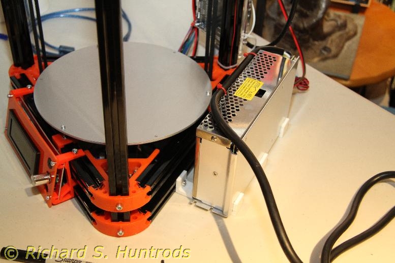
I’ve been working with the FLSUN delta printer I built from a kit this week, and although it has printed a few of the test cubes, it’s still not quite fully functional yet.

It turns out delta printers are a lot faster than cartesian (x,y,z) printers, but with that speed comes some rather unique challenges. The first is that the printer, being tripod and pendulum based, really wants to print in an arc. To counter this, the software needs to know a lot of details about the printer, such as segment lengths and arcs in order to calculate various angles and offsets to use when printing.

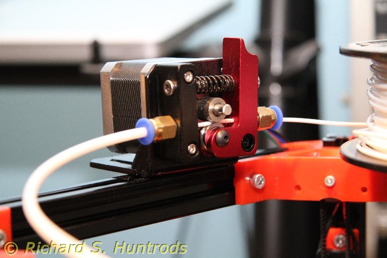
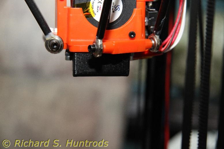
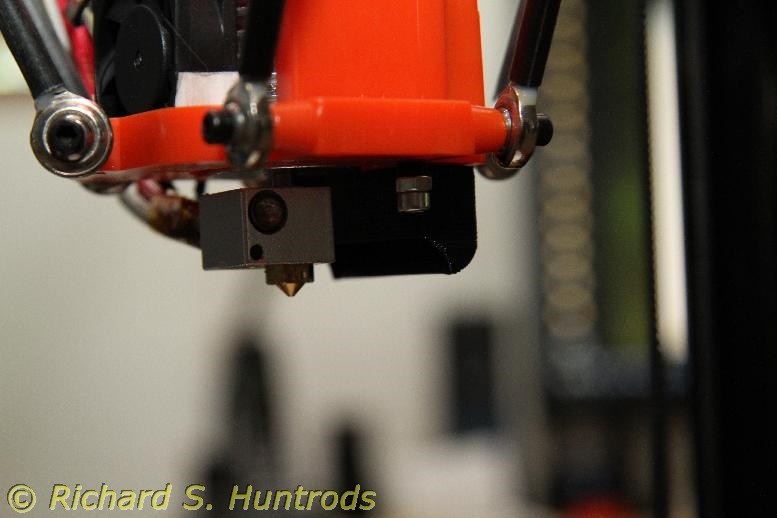
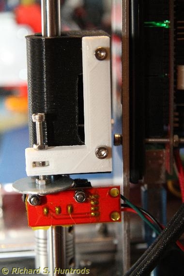
Fortunately the delta code firmware I’m using (Marlin 1.1) now has an auto calibrate feature that works with the built-in z-probe on the FLSUN delta. Not all deltas have the z-probe, but it’s easy enough to add to any printer. Basically it’s a microswitch down near the extruder that detects when the extruder is near the print bed. On the FLSUN, the switch is triggered by a rather ingenious lever mechanism built into the extruder mount. When the tip touches the bed, it rocks slightly and trips the microswitch. You can fine tune the triggering pressure so that it’s very accurate. There is one compensating measurement you must take, and that’s how much deflection occurs when triggering. That is, the extruder doesn’t just touch the bed, it touches it a bit MORE than when printing to tip and trigger the switch. You need to know (in mm) how much this extra movement is so the software can compensate when calculating actual bed height.

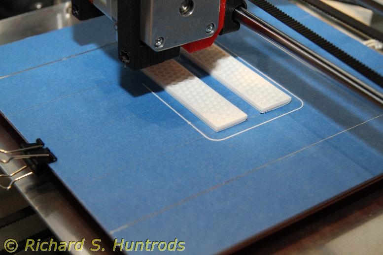
The auto calibrate touches the bed in a set number of places that can be programmed (n*n, with n=4 as default). It can then calculate various angles and offsets that you then either save in the printer firmware eeprom or hand code into the software. I chose to hand code. The default calibration runs until a set standard deviation is achieved, so it’s quite accurate.

Once the auto calibrate is done and the information encoded in the firmware and uploaded to the printer, you can print.

My first prints were terrible. I quickly realized the extruder calibration was off. Extruder calibration is done with auto calibrate but must be done separately. Mine was barely moving, so after some experiments and adjustments, I got the correct parameter (stepper steps per mm of filament) and that was OK.

However, the next several prints were all still bad. I quickly found one of the three end stops that controls the position of the extruder was loose. After adjusting and tightening, things were much better, but there’s still a problem with the print.

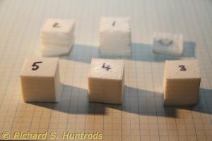
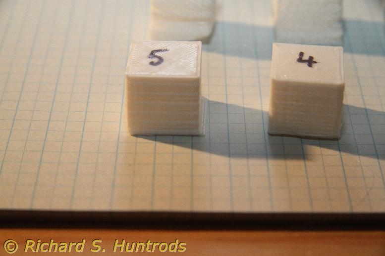
The first few layers (about 1mm or so) are offset from the rest of the print in one direction. It’s consistent and repeatable at this time. The rest of the cube is perfectly straight, so it’s a “first layer” problem. So far I have not found any solution on the internet.

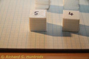
One hint that I’ll be pursuing is that the height measurement of the cube is only 19mm, while the sides are both 20mm perfectly. That implies again a “first layer” problem, possibly too hot. I am also considering the fact that this printer is incredibly fast. It’s almost twice the print speed of my first (cartesian) printer. It’s possible that it is simply printing the first few layers too fast, which may also affect the temperature of those first layers.

My next steps are to compare speed parameters between Marlin 1.1 (my current firmware version) and Marlin 1.0 (supplied with the printer) and my cartesian printer (also Marlin 1.1, but much slower settings). I will also try slowing the first layer in slic3r as a quick test. If slowing the initial print speed works, then that will be great. For now it’s a wonderful printer that has yet to realize all it’s benefits (and yet to make it’s first perfect print). 

Letting the cat out of the bag (3d Printer)

OK, so I’m letting the cat out of the bag. Back in August I decided that I really wanted to try the new delta printers. They come primarily as kits, though you can buy one already  built if you are made of money. I’m not; besides I like building kits.

After much research including print and video reviews as well as many build videos, I chose the FLSUN Kossel Delta printer. There were several delta printers of almost identical value, but I chose this printer for the primary reason that it is “fulfilled by Amazon”, meaning that it comes from a N. American warehouse, not from China. That in turn means that it will arrive quickly. The price was also an incredible deal compared to many others.

It arrived in quick order, and everything was there. It was very well packed, and relatively easy to assemble. I did not make an “assembling of” video because those are pretty similar and all pretty boring, even at high speed. For the most part I followed the instructions to the letter, though I did deviate a few times when I could clearly see a better path. I only had to undo/redo one step, and that only because I wasn’t paying attention to the orientation of the extruder during assembly.

Some of the final steps were less than optimum, in my opinion. Mostly these involved routing and bundling of wires, and location of the main board and power supply. In the end I designed and printed some brackets to hold the power supply securely in a very nice location. I printed these on my other printer. I also designed and printed a spool holder to sit on top. There were available designs on Thingverse, but I really didn’t like them. I do like mine.

I will post photos of the spool holder and the power supply brackets later this week, as well as photos of the printer.

Once together, I did all the set-up, prep and calibration steps.

I still didn’t like the way I’d wired the power supply. I also didn’t like the fact that the power supply did not have an on/off switch, so I bought a switch/cord/fuse receptacle from Amazon (very inexpensive) and then printed a housing for it that sits off the end of t he power supply. It looks great and secures the cord (and all connections) inside the housing. Plus, now there’s an on/off switch for the printer.

I’ll post photos of the switch and housing later this week.

I have yet to make my first print with the printer, but it should happen quite soon.

Photos of recent 3D prints

As promised in my last post, here are some photos of the weight plate collar and the new regulator flow knob. Also a photo of the old knob for comparison.

Dacor Fury small knob

Dacor Fury new larger knob

Weight plate collar (the yellow spot marks an original collar)

This is a set of base brackets I printed to hold my PiDP8 kit at a better viewing angle (design from Thingverse)

Still designing and printing

I made a few things this past week, and designed (and made) a few others.

First, I didn’t like the stark white of the new Dacor Fury flow adjustment knob, so reprinted it in black. I also flipped it so the square hole was on top for a better print of that side. When done it fitted perfectly and has already been tested in the water. It works perfectly.

I loaded cave line onto the dive spool and also took it in the water. It held up perfectly but time will tell how it holds up.

I also designed and printed a replica of the weight plate ring for my weight bench. The ring is a complex plastic part that sits in a hole in the weight plates and keeps things from banging loudly when in use. Each plate requires three (on for the center bar and two for the side slide bars) and many were missing or broken when I bought the (used) weight bench. I tried contacting the manufacturer in eastern Canada, but the bench was made in 1995 and they had no records for it at all! I designed one in Tinkercad and it printed perfectly. It’s now on the 50lb plate so that it can get some everyday use to see how it holds up before I print more.

I also designed and printed some clips for the cats’ litterbox. It’s 10 years old and the originals broke. The printed ones fit perfectly and so far are holding up very well.

Finally over a week ago now I designed some small plastic ‘buttons’ to cover assembly holes in a set of drawers Linda bought for her sewing room. You know the ones – the small white plastic 1/2in buttons that go in the screw assembly holes in pre-pack particle board furniture. This one was missing all but one (of 8) so I used it as a template to make 9 new ones. Some had to be white glued in place as the holes had enlarged, but all are on now and look great.

I notice that my photos weren’t ready for uploading, so I’ll add them soon. (New reg knob, loaded dive spool, weight ring and litterbox clips).


Lastly, some news on filament. The white AMZ3D filament was working very well, with only occasional snags. Thinking about it, I realized the spool did get loose during the coathanger holder creation. I decided to open the AMZ3D black filament and be very careful loading it. As a result, I’ve been able to print many things, some with over an hour print time, without any snagging at all. It would seem that a) this AMZ3D filament is awesome stuff, and b) loading procedure is critical – you cannot get any loosening of the filament when loading or you will get snags. I really like the AMZ3D white, but I absolutely love the AMZ3D black. I even ordered another roll.

3D Printing: more designs, fixes, prints and stuff

After printing the regulator flow knob, I was rather pleased with myself. Then the black filament ran out while printing a coaster, so I changed to the new AMZ3D filament I bought recently. I decided to try the white. The spools are smaller, both the hole and the width, so my current ABS pipe holder would not work.

I tried printing “from the box” as I’d done with the MG Chemicals filament, but it didn’t work with the smaller, side opening box. Instead it jerked the z axis at the start of a print and threw off the bed adjustment!

I managed to get that fixed, but took the opportunity to change the bed mount system to now use nylock nuts for greater vibration resistance. While I was at it, I again ran into the mess that is setting the z endstop.

So I decided to design a new adjustment system for the endstop. It uses the same new z endstop I printed a while ago and have been using with good results, but added a screw adjuster.

I designed the plastic to hold the screw using Tinkercad, then printed it. The first one wasn’t correct, but allowed me to see the problem and correct the design. The second was perfect. I mounted it on the non-motor x axis end that rides the vertical bar. One problem I discovered is the screw could not possibly touch the z endstop microswitch. I needed a lever, but turning the screw would spin the lever. I needed a round lever, a.k.a. a washer. Finding a suitable washer, I assembled the z endstop adjustment system and in the first test it worked perfectly. Better than that, it is now easy to make micro adjustments to the z endstop for quick adjustments of the extruder height. Photos attached.

Then I needed a new filament holder. During these test prints, I used a holder I made quickly from a bent metal coathanger (see photos) clamped to the table. It worked but looked like crap.

Today I designed a new spool holder, also out of a coathanger and a length of broomstick, but modified it based on what was wrong with the first one. It works great, and again photos attached.

All in all a great end of the week.