More 3D Printed goodies

A week ago the ancient electric pencil sharpener died. The motor could be heard spinning when  a pencil was inserted, but no sharpening action. I took it apart to find the large gear that drives the sharpening mechanism was broken in two pieces. As I shook it out, it broke again. Time for a new unit? Not with a 3D Printer! Before I gave up on this item, I would try and print a replacement gear.

Designing gears is not fun, but the on-line CAD program Tinkercad had a community supplied gear builder. I took measurements from the broken gear, counted the teeth (70) and designed a new one. My first print wasn’t correct. The broken gear did not reveal the drive slot was only partially into the gear, with a round shaft for the rest. Once I had one new gear with the slot all through it was easy to see what needed to be done. The next gear fit well and worked. It’s noisy, but it works.


The next challenge was designing an optical connector for my underwater camera housing. The very expensive part from the manufacturer (double any equivalent price) screws onto an optical fitting on the housing. The bare cable has an optical end, but must be mechanically connected to the strobe and housing. On the strobe it’s a simple hole, but I needed something similar on the housing. Again using Tinkercad, I was able to design a simple connector. It took a few tries to get the sizes correct as things must be tight but still fit. After 5 tries I had a good fit. Now to take it to the water for a test dive.  The optical port is shown mounted on the housing on the upper center left.

FLSUN delta printer update for 2017-10-24

Yesterday the new aluminum extruder came from amazon.ca for my delta printer. It was nicely packaged and although the instructions could have been better (b&w photos aren’t great for assembly), they were adequate.

I removed the original plastic-parts extruder and installed the new extruder. It was immediately obvious the mechanism is much better than the original. The toothed wheel is a much finer tooth count, and the idler wheel with notch is much smoother. The spring tension is not adjustable either from close examination nor from the assembly photos, but seems to work in an excellent fashion.

The only hiccup was when I tried to test the calibration. No matter what, I could not get it to extrude. Finally, after much frustration, I realized the two settings in pronterface are not extrude lenght / reverse length, but rather settings for 1.extrude/reverse length and 2. extrude/reverse SPEED. Setting it from the default of 10mm/min to 120mm/min (2mm/sec) was all it took to see some action. Unfortunately the operation was now reversed due to placement of the idler compared to the original extruder.

Fortunately there’s a setting in the configuration.h file for stepper direction which includes the extruder stepper. Flipping the binary option caused the extruder to properly extrude/reverse. Due to the finer gear spacing, asking for 1cm gave 1.4cm. It’s a quick parameter change to fix that and confirm requesting 1cm now gives 1cm extrusion (and retraction).

Finally, I reconnected the filament and tube to the hot end, burning myself severely in the process (2nd degree on a finger which slipped). Once connected I made a test print of the benchy (boat). The first layer is still off, but now at least I can make adjustments knowing the extruder is functioning properly.

Final lesson learned: 185C is VERY, VERY hot. It will cause an instant 2nd degree burn as I found out to my distress. Fortunately immediate cold water followed by ice for 2 hours has reduced the damage significantly.

Letting the cat out of the bag (3d Printer)

OK, so I’m letting the cat out of the bag. Back in August I decided that I really wanted to try the new delta printers. They come primarily as kits, though you can buy one already  built if you are made of money. I’m not; besides I like building kits.

After much research including print and video reviews as well as many build videos, I chose the FLSUN Kossel Delta printer. There were several delta printers of almost identical value, but I chose this printer for the primary reason that it is “fulfilled by Amazon”, meaning that it comes from a N. American warehouse, not from China. That in turn means that it will arrive quickly. The price was also an incredible deal compared to many others.

It arrived in quick order, and everything was there. It was very well packed, and relatively easy to assemble. I did not make an “assembling of” video because those are pretty similar and all pretty boring, even at high speed. For the most part I followed the instructions to the letter, though I did deviate a few times when I could clearly see a better path. I only had to undo/redo one step, and that only because I wasn’t paying attention to the orientation of the extruder during assembly.

Some of the final steps were less than optimum, in my opinion. Mostly these involved routing and bundling of wires, and location of the main board and power supply. In the end I designed and printed some brackets to hold the power supply securely in a very nice location. I printed these on my other printer. I also designed and printed a spool holder to sit on top. There were available designs on Thingverse, but I really didn’t like them. I do like mine.

I will post photos of the spool holder and the power supply brackets later this week, as well as photos of the printer.

Once together, I did all the set-up, prep and calibration steps.

I still didn’t like the way I’d wired the power supply. I also didn’t like the fact that the power supply did not have an on/off switch, so I bought a switch/cord/fuse receptacle from Amazon (very inexpensive) and then printed a housing for it that sits off the end of t he power supply. It looks great and secures the cord (and all connections) inside the housing. Plus, now there’s an on/off switch for the printer.

I’ll post photos of the switch and housing later this week.

I have yet to make my first print with the printer, but it should happen quite soon.

Photos of recent 3D prints

As promised in my last post, here are some photos of the weight plate collar and the new regulator flow knob. Also a photo of the old knob for comparison.

Dacor Fury small knob

Dacor Fury new larger knob

Weight plate collar (the yellow spot marks an original collar)

This is a set of base brackets I printed to hold my PiDP8 kit at a better viewing angle (design from Thingverse)

Still designing and printing

I made a few things this past week, and designed (and made) a few others.

First, I didn’t like the stark white of the new Dacor Fury flow adjustment knob, so reprinted it in black. I also flipped it so the square hole was on top for a better print of that side. When done it fitted perfectly and has already been tested in the water. It works perfectly.

I loaded cave line onto the dive spool and also took it in the water. It held up perfectly but time will tell how it holds up.

I also designed and printed a replica of the weight plate ring for my weight bench. The ring is a complex plastic part that sits in a hole in the weight plates and keeps things from banging loudly when in use. Each plate requires three (on for the center bar and two for the side slide bars) and many were missing or broken when I bought the (used) weight bench. I tried contacting the manufacturer in eastern Canada, but the bench was made in 1995 and they had no records for it at all! I designed one in Tinkercad and it printed perfectly. It’s now on the 50lb plate so that it can get some everyday use to see how it holds up before I print more.

I also designed and printed some clips for the cats’ litterbox. It’s 10 years old and the originals broke. The printed ones fit perfectly and so far are holding up very well.

Finally over a week ago now I designed some small plastic ‘buttons’ to cover assembly holes in a set of drawers Linda bought for her sewing room. You know the ones – the small white plastic 1/2in buttons that go in the screw assembly holes in pre-pack particle board furniture. This one was missing all but one (of 8) so I used it as a template to make 9 new ones. Some had to be white glued in place as the holes had enlarged, but all are on now and look great.

I notice that my photos weren’t ready for uploading, so I’ll add them soon. (New reg knob, loaded dive spool, weight ring and litterbox clips).


Lastly, some news on filament. The white AMZ3D filament was working very well, with only occasional snags. Thinking about it, I realized the spool did get loose during the coathanger holder creation. I decided to open the AMZ3D black filament and be very careful loading it. As a result, I’ve been able to print many things, some with over an hour print time, without any snagging at all. It would seem that a) this AMZ3D filament is awesome stuff, and b) loading procedure is critical – you cannot get any loosening of the filament when loading or you will get snags. I really like the AMZ3D white, but I absolutely love the AMZ3D black. I even ordered another roll.

3D CAD Software… so far

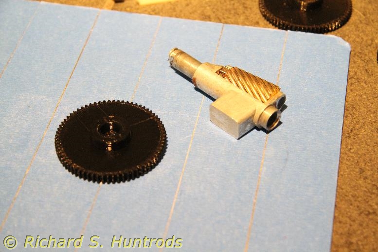
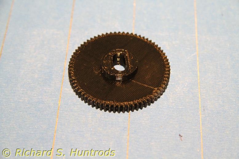
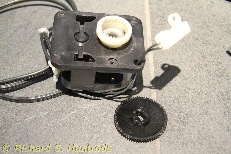
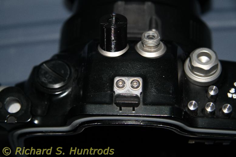
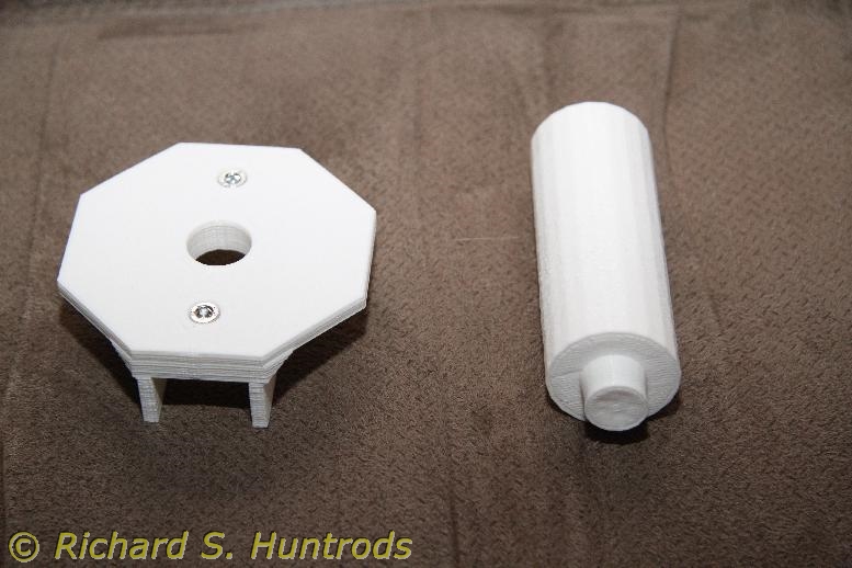
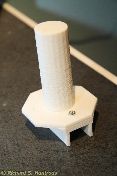
As mentioned in a previous post, it became necessary to create my own design for the underwater housing lens focus gear as nothing available was the correct size. After some measurements and paper modelling, I needed to create a software model that I could print.

Enter the CAD software. There are a number of programs available, ranging from free to ouch. I restricted my initial examination to free, as I hate spending money when I don’t even know if something will do what I need. While there are trial copies, the learning curve for most CAD software is just steep enough that don’t want to spend time learning something that may not be up to the task.

There were a lot of recommendations for Autodesk’s 123-Desigh program, but all attempts to find it took me to an Autodesk site for Tinkercad. This is a free program that’s 100% browser based. Nothing is downloaded to the PC, and all design files reside in “the cloud” under an Autodesk account.

I tried the intro tutorials, and it seemed pretty easy to use. So easy, in fact, that I had a first rough design done after less than 20 min. More experimentation and I managed to destroy that design – there seems no way to abandon unwanted work. It wants to save whatever you do no matter what. The problem is that while there are many levels of undo, there weren’t enough to rescue my design.

I started over and found it even easier the second time. 10min and I had the same design. Refinements and additions were easy, so I have to say the program Tinkercad is excellent for simple CAD work. Tinkercad will save the design as a printable file (STL) on the PC, but there is no way to save design files locally.

And… I really hate not being able to save my work on my PC. So back to google for more options. The second program is related – it’s Autodesk’s Fusion 360, also highly rated. It’s more complex than Tinkercad, offering many more features. However, without even a tutorial I was able to bang out the same design using Fusion 360 in about 20 min. One nice feature is that it bevels edges of holes, meaning that it’s design doesn’t have undercuts in my work the way Tinkercad’s design did. This in turn means slic3r does not have to add support structures to the design in order to print it. That’s a saving in print time and object cleanup once printed.

Fusion 360 also offers a way to save the design as a STL (design) file to the PC, as well as export a DXF (autocad drafting model) file via an on-line link or a proprietary model file (F3D), which is a bonus.

So Tinkercad is simple but works, and Fusion 360 is more complex and powerful and also works. Both save printer files (STL) but only Fusion 360 will save a model file on the local PC.

Finally, I looked at Creation’s Sketchup. There’s a free version, and a Pro version. They also highlight the fact that the Pro version is free to academics, so I had to get that. After losing the registration email in the university’s spam filter for a while, I was able to download and register the program.

I have only started to work with Sketchup Pro, and will report more in the future. After viewing the initial tutorial videos, I’d say it looks pretty promising, but will know more as I use it.


Finally, the elephant in the room. Blender. Everyone raves about blender. It’s the default ‘go to’ CAD program. Except… it’s not. It’s a program designed for 3D design, especially for artwork and animation (gaming). It’s good for 3D modelling for printing, but the learning curve is almost vertical.

I’ve had it on my PC since I started the final build on my printer, and even after multiple tutorials and attempts at using it, I’m nowhere, and have given up. It’s just too much program for what I require, and that just doesn’t justify the huge learning curve. It doesn’t help that almost every activity has an unconventional keystroke or mouse procedure to access it. It’s like the music software Finale back in early Mac days – really excellent but you have to be totally dedicated to it in order to learn and use it. And these days, that’s not me.

3D Printing update

I’ve been fairly busy the last week or so; first fixing the z axis bolts and then the z endstop. Adjusting it has been a bit of a pain, especially when a print starts too far from the bed and you have to scrap it. Actually adjusting the endstop is difficult as it’s intentionally stiff so it won’t move by accident and you need 1mm or less resolution in the adjustment. I can see why many have elected to design endstop mods that include a fine tuning bolt. I may do that, but there are other options…

Doing more digging I found parameters in slic3r that allow me to ‘manually adjust’ the starting position offset to compensate if necessary. I now have the bed level and proper height, so don’t need to use the parameter at the moment, but it’s nice to have it. A “virtual fine tuning bolt” if you will.

There are also parameters to create fill for undercuts. I’ve had a few prints fail due to undercuts in the design, and this should help.

In the meantime, I’ve now printed several ‘toys’, including several cubes, an easter island head and a small skull, plus a toy soldier for a game that seems popular.

For more interesting projects, a few weeks ago I printed a ball mount for my SOLA 1200 video light that works very well. Last week I printed a quick connect ball mount for my underwater housing. It was two parts, and there were undercuts that didn’t print properly, but it does fit and work. I bought some cyanoacrylate glue (Loctite 420) which works very well gluing close facing items.

Finally, after much testing and frustration, I found one gear that would work in my other underwater housing as a focus gear. It needed scaling (120% x & y) and also additional cylinders to fit the lens. After trying many things, I bit the bullet and tried designing it myself using TinkerCad. TinkerCad is from Autodesk and is a 100% on-line browser based tool. It was easy to get working and took little time to design my set of cylinders to fit the gear. Trial #1 broke (too thin on the upper cylinder) and the gear was too thick. I redesigned the cylinders and re-scaled the gear, and after gluing it works and fits perfectly.

Later I designed the same cylinder set in Autodesk’s Fusion 360, which is a bit more complex a program than TinkerCad, but resides on my PC which I prefer.

All in all a productive and fun week with the printer.

3D Printer – now better

As I mentioned in the last blog post, I printed a new z-endstop for the printer to replace the one zip-tied in place. The problem with the zip tie stop was the zip tie was on a smooth rod, and it would move if bumped by the carriage.

The first one I printed looked pretty nice; it mounted on one z-axis motor and was designed to hold the microswitch up to contact a printed adjustment piece. The problem with this type was first the mount holes were totally wrong for the style of microswitch I had (too close) and the triangular shape of the holder prevented proper holes from being drilled. The adjuster also would not fit on my x axis motor, so the whole thing was a dud.

I kept looking and finally found a printable small triangular mount that was easy to print, and captures the microswitch perfectly. It takes up almost no room. I had to print this one using a cobbled together solution as I’d removed the zip-tied endstop trying to get the first printed one to work. The printing was not great (the holes were not centered properly) but I was able to drill it and once installed it works perfectly.

Since then I’ve printed a few things, and had a few failures due to my newness at 3d printing, but it’s all good and fun again.

3D Printer – It’s dead, Jim… no wait! IT’S ALIVE!!! (and a lesson)

Yea, I know. Really, really cheezy title. Tough.

Last week I went to make a print for my underwater video light – a quick disconnect ball mount so I can leave the ball mount permanently attached to the video light no matter what housing I use. It looked pretty straightforward, and I started to print…

… only to find it was pooping it’s thread from about 5mm instead of onto the bed. I checked and confirmed the height was off, so corrected it. It did it again! I tested the x-axis extruder height, and it was also off level. This was very strange as nothing had changed, but as I was checking I discovered the z axis was moving when I touched it. It is NOT supposed to do that.

More checking confirmed the bad news – one of the nuts that is part of the z axis was totally stripped. You could take the threaded rod and zip it back and forth holding the nut. The other nut was OK, but for now the printer was down.

A detailed analysis plus a bit of an “aha” moment involving the same threaded rod and the video light made me realize the so-called 5mm threaded rod was actually a 10-32 imperial thread. It was not metric at all. I have 10-32 nuts, bought as part of the video light project, and they fit perfectly on the threaded rod. More interestingly, the 5mm nuts showed significant “lash” on the rod while the 10-32 nuts showed almost none.

The only problem was the 10-32 nuts were too large to mount on the printer. I tried epoxy, but it just peeled off the PLA mount once cured. All the fancy stores were closed Saturday, including one that was supposed to be open but could not bother to post that on the website or make an answering machine message, so I was out of luck until today.

This morning I went to Fastenal in Nanaimo, looking for “threaded rivets” a.k.a. rivet nuts. These are marvelous threaded tubes about .5 in long by whatever thread you want. They would solve the problem perfectly. Unfortunately, they were out of stock and it would be a week for more. However, they did have true 5mm stainless threaded rod and stainless 5mm nuts. I bought both, came home and cut the rod to length and installed it. With the new nuts, it was back to a working printer in a matter of about an hour.

Once rebuild, I had to level the x axis again. The height is controlled by the two z axis threaded rods, and though you can get really close by evening the nuts before you assemble it, it’s best to fine tune with a strip of paper and the extruder.

The first print was again the 20mm cube, as that’s a really good test of the printer and allows me to verify all dimensions. It turned out the z face was high – 20.05mm and not 20mm, so I grabbed the internet and checked thread pitches. It turns out they are most certainly NOT the same. 10-32 is 32 tpi (thread per inch), or 0.03125 / inch. Metric 5mm is usually 0.8mm pitch, which is 0.03150. It seems so close, but when dealing with 0.1 mm it’s not close enough. The 0.8mm pitch is just a tad coarser – equivalent to 31.75tpi. I adjusted the firmware print constant to account for the difference, and the second 20mm cube was exactly 20mm as it should be.

Now I’m printing a new z-endstop for the printer. The current z endstop is just zip tied in place, and it would move while I was leveling the x axis. This is not good, so I found some printable ones and will see what I can devise.

At least the printer is again functional, which is a great relief to me.