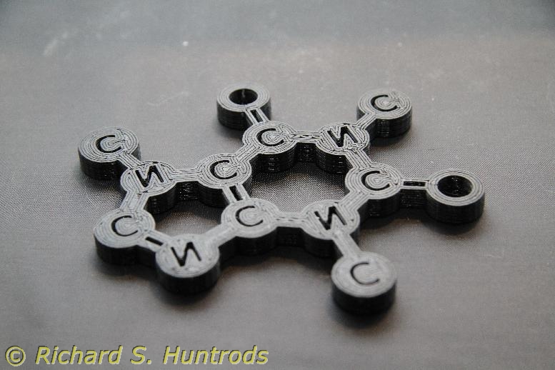
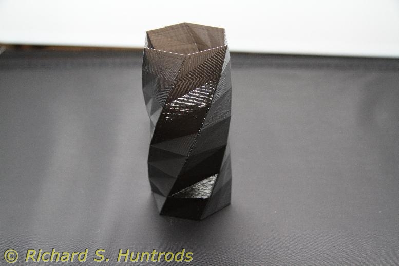
The last many posts have been text only, without the benefit of photographs. To compensate, here are a set of photographs of the “keepers” – 3D printed objects that have turned out well.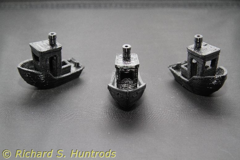


Category Archives: Robotics
3D Printing – it happened again
Yesterday I spent quite a while printing with great success, until the last print of the evening. By now the printer had been laying down filament for a few hours, and about 3/4 through printing a coaster, I heard the dreadful clicking sound that indicates a fouled nozzle. I immediately shut things down and called it a night.
Later on, while considering why the filament would jam after all the corrective actions I’d taken, it came to me.
My printer has one fan, which came as part of the extruder assembly I had purchased. Seeing there was a fan connector on the RAMPS board, I connected the fan there and found the slicer software would control that fan. The two settings were “always on” and “auto”. I had chosen auto.
Reading about auto mode indicated the fan speed was a function of print time per layer, determined during the encoding process. I thought this a bit odd, but figured it would be fine.
I asked my friend which setting he used, and indicated that his extruder fan was wired directly to 12v, and that the slicer setting was for a print cooling fan, not the extruder fan. Further reading of the RAMPS manual verified this. The parameters affecting the auto setting now made more sense to me, as you would want more cooling on a print where the layers are taking longer to print.
Further reflection also suggests why I was having problems. First, all my jams occurred after much printing, when things had been hot for some time. With the extruder fan not running all the time (auto setting), the heat from the extruder hot end would gradually travel up the metal feed tube. Eventually, the filament in the tube would become warm further from the nozzle. When this happened, it would be harder to feed the warm filament and it could resist and jam, much like trying to push a piece of hard spaghetti vs. cooked spaghetti. The purpose of the fan is thus to keep the feed tube cool so the filament remains cool and feeds properly.
Later today (after my dive) I will rewire the extruder fan to the 12V supply so that it’s running whenever the printer is on.
3D Printing – disaster and recovery
I have been experimenting with print settings for my 3D printer, to overall good success, until things failed.
The printer uses 1.75mm filament, which is heated and then extruded through a 0.4mm nozzle. However, it is possible to set the layer height to any value from 0.1mm to 0.4mm through the slicer software. The default was 0.3, but lower values are supposed to create smoother and more detailed prints.
Last week I stared printing with 0.2mm layer height, and things were going well. The prints did seem more detailed, but then disaster. During one print, I started to hear a clicking sound from the extruder. This is not good as it indicates the extruder is jamming somewhere and not feeding properly.
Checking the print I could clearly see that it had stopped printing. I killed the print and had a closer look. Filament was coming out the extruder gears where it should be feeding the heater & nozzle. In the end I had to completely disassemble the extruder so I could access the stepper motor, gear, pulley and filament jam. The extruder stepper was also very hot, which is not normal.
It took an hour, but I was able to disassemble, clear, and then reassemble the extruder. Unfortunately while reinstalling it I broke one of the printed PLA clips. I was able to glue it, but would need to print a replacement in the future.
With the extruder cleared, I printed the 20mm box without problems, so then started to print an octopus model. Midway through the print, the extruder started clicking again. This time I killed the print before the jam was bad and was able to remove the jammed filament without difficulty.
However, it left me with a problem: why was the extruder now jamming when it had been working fine for weeks?
I searched the internet for “filament jam” and found several common causes for jams, but only one really seemed to apply to my situation.
I had noticed the base layer was thin, and wondered if the nozzle height was too low. This is one common cause of jams, as the low height prevents smooth flow of filament in the first layer. After testing I realized the nozzle needed to be raised by 0.1mm or more. This is not easy with my current z endstop, but there’s a parameter in the slicer software to include a “z offset”. I did this and the base layer was much better on some test prints.
However, this was not the case before the first jam. I had checked, and removing and reinstalling the extruder had changed the nozzle height just enough to cause the problem. But that did not explain the first jam.
I therefore reflected on the classic problem solving approach, “what changed?”. The one thing I had changed was lowering the layer height from 0.3mm to 0.2mm. As I considered this, it seemed to me a puzzle – why would you think you could get 0.2mm from a 0.4mm nozzle? Should not the nozzle diameter dictate the layer height, not the other way around? You do want adhesion between layers, so it seems logical to use a number like 0.3mm for a 0.4mm nozzle, just to squeeze the layers together a bit. I had been using 0.3mm for weeks without problems, so the logical next step was to return to 0.3mm and see if filament jams ended.
I did that a few days ago, and since then have printed more objects than I have in the weeks before. Every object has printed very well, with good quality, and NO JAMS. So 0.3mm it shall stay. I even printed the new extruder clips and have installed them.
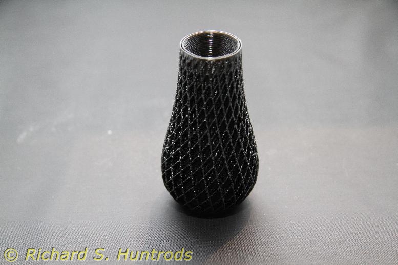
I’ve even stared playing with “vase mode”, where prints are a single layer thick and a continuous spiral of filament. The vases are paper thin, but really fun to make.
So it would seem that I’ve solved my filament jam problem.
3d Printing – chicken and egg
Last week I designed another gear item for my camera and underwater housing. The 60mm focus gear works perfectly, but I was curious if my 17-85mm zoom lens would work in the housing with the current port.
The problem with ‘just trying it out’ is that while I can put the lens on the camera and fit it in the housing & port, I know that at 17mm there will be vignetting as it’s not a dome port. What I really wanted to test was whether or not it could zoom enough to be useful. However, just trying to install the lens zoomed might not fit. What I needed was to be able to actuate the zoom with a proper zoom gear.
Which meant designing and printing a proper zoom gear. Based on my focus gear design, I created a new model based on the focus gear cylinders, but sized for the zoom lens which had quite a bit larger diameter. The zoom lens also has a noticeable bump where the autofocus switch is located. After a few test prints, I completed the final design and printed it. The first print was very good, and fit perfectly.
With the zoom gear complete, I was able to install the lens on the camera (with zoom gear) and then into the housing on wide angle. Once in, I could clearly see the vignetting, and then tested the zoom gear. Again, it worked perfectly, but the lens quickly bumped the end of the port. Sadly, it was nowhere near close-up, and still showed vignetting. In the end I will not be able to use the zoom lens in the underwater housing with the current macro port, but if I ever win a lottery and buy a dome port, it will work perfectly.
In other news, I’ve been watching a lot of youtube videos on “delta printers”. These are 3d printers that employ a triangle pillar system to control three stepper motors, which in turn move a trapeze supported on the three pillars. It’s a very fluid moving system, and most fun to watch. There is one new version that has one extruder but three filaments, and can mix colors on the fly!
Watching build videos it’s clear that some of these printers are extremely well designed for kit building. The only downside at the moment is there are very few inexpensive kits that offers both heated bed AND multiple extruders. The best kit I’ve found so far (for build quality) comes with only one extruder and no heated bed. While the heated bed is pretty easy to add, conversion to multiple extruders is a very advanced topic. The other downside is many come direct from China, and that’s always a bit of a crapshoot when it comes to the thing actually arriving at my door. So far I’m around 90% but still… to lose a $300-$400 kit would not be good.
Still 3D printing after all these days…
Some notes on what’s been happening in the 3D printer world. Mostly it has to do with software. Here are the highlights:
Tinkercad is still by far the easiest program to create simple designs for test printing and design.
Fusion 360 is slightly superior to Tinkercad but ONLY because it ‘automatically’ bevels holes. I realize that’s just a default parameter setting, but still – it means my final design has a bevel when an interior hole is reduced, which means no support structure required and thus faster/easier printing.
But – Fusion 360 is still a bit of a pain to use, especially compared to Tinkercad. I usually end up deleting my first effort and trying again (and again) to get the desired final result. It’s annoying because the options/interface is so horrid.
Example: I ‘accidentally’ created two bodies when I wanted just one. I don’t know how I did it, and can’t reproduce the case, but once created I could NOT find any way to merge the two bodies back into one. It should be as easy as “select both, press ‘merge'”, but there’s no ‘merge’ function that works this way.
Finally, Sketchup. What a horrid beast of a program so far. Not only is it quite counter-intuitive to build anything like a cylinder, but I cannot find a way to export the result as a printer file. Not looking good for Sketchup at this point.
As for printing, I did discover one odd behaviour about slic3r. If you add multiple designs, say add a gear to a cylinder, or just add two of the same thing and arrange them, the resulting gcode file contains the complete model. HOWEVER, if you save the stl (model) file, only the last thing added gets saved. YOU CANNOT SAVE A COMPOSITE MODEL in Slic3r. That’s a pain, but I can live with it now that I know.
Other news: I built another gear model for the Canon camera. This one is a zoom gear for the 17-85mm zoom lens. The gear is the same one used for the 60mm focus gear I built last week, but the cylinder ID was larger to accommodate the larger diameter of the zoom lens. There were a few other adjustments as well, but the final zoom gear fits and functions perfectly.
I tested the focus gear in the housing underwater last weekend, and will try the zoom gear and lens in the housing this week. If it fits and works, I’ll test it underwater this Sunday.
Note: The zoom lens is not designed for this port, but the port is longer than needed for the 60mm lens, and so I thought I’d like to try it on the camera in the housing. Before I could do that, I really needed the zoom gear to be able to actually test the zoom function in the housing. It’s a ‘chicken and egg’ situation really. Also, until I had any working gear, there was no point worrying about the zoom lens. That dictated the 60mm focus gear being designed and printed first. Once that worked, the way was clear to go for the whole zoom test.
3D CAD Software… so far
As mentioned in a previous post, it became necessary to create my own design for the underwater housing lens focus gear as nothing available was the correct size. After some measurements and paper modelling, I needed to create a software model that I could print.
Enter the CAD software. There are a number of programs available, ranging from free to ouch. I restricted my initial examination to free, as I hate spending money when I don’t even know if something will do what I need. While there are trial copies, the learning curve for most CAD software is just steep enough that don’t want to spend time learning something that may not be up to the task.
There were a lot of recommendations for Autodesk’s 123-Desigh program, but all attempts to find it took me to an Autodesk site for Tinkercad. This is a free program that’s 100% browser based. Nothing is downloaded to the PC, and all design files reside in “the cloud” under an Autodesk account.
I tried the intro tutorials, and it seemed pretty easy to use. So easy, in fact, that I had a first rough design done after less than 20 min. More experimentation and I managed to destroy that design – there seems no way to abandon unwanted work. It wants to save whatever you do no matter what. The problem is that while there are many levels of undo, there weren’t enough to rescue my design.
I started over and found it even easier the second time. 10min and I had the same design. Refinements and additions were easy, so I have to say the program Tinkercad is excellent for simple CAD work. Tinkercad will save the design as a printable file (STL) on the PC, but there is no way to save design files locally.
And… I really hate not being able to save my work on my PC. So back to google for more options. The second program is related – it’s Autodesk’s Fusion 360, also highly rated. It’s more complex than Tinkercad, offering many more features. However, without even a tutorial I was able to bang out the same design using Fusion 360 in about 20 min. One nice feature is that it bevels edges of holes, meaning that it’s design doesn’t have undercuts in my work the way Tinkercad’s design did. This in turn means slic3r does not have to add support structures to the design in order to print it. That’s a saving in print time and object cleanup once printed.
Fusion 360 also offers a way to save the design as a STL (design) file to the PC, as well as export a DXF (autocad drafting model) file via an on-line link or a proprietary model file (F3D), which is a bonus.
So Tinkercad is simple but works, and Fusion 360 is more complex and powerful and also works. Both save printer files (STL) but only Fusion 360 will save a model file on the local PC.
Finally, I looked at Creation’s Sketchup. There’s a free version, and a Pro version. They also highlight the fact that the Pro version is free to academics, so I had to get that. After losing the registration email in the university’s spam filter for a while, I was able to download and register the program.
I have only started to work with Sketchup Pro, and will report more in the future. After viewing the initial tutorial videos, I’d say it looks pretty promising, but will know more as I use it.
Finally, the elephant in the room. Blender. Everyone raves about blender. It’s the default ‘go to’ CAD program. Except… it’s not. It’s a program designed for 3D design, especially for artwork and animation (gaming). It’s good for 3D modelling for printing, but the learning curve is almost vertical.
I’ve had it on my PC since I started the final build on my printer, and even after multiple tutorials and attempts at using it, I’m nowhere, and have given up. It’s just too much program for what I require, and that just doesn’t justify the huge learning curve. It doesn’t help that almost every activity has an unconventional keystroke or mouse procedure to access it. It’s like the music software Finale back in early Mac days – really excellent but you have to be totally dedicated to it in order to learn and use it. And these days, that’s not me.
3D Printing update
I’ve been fairly busy the last week or so; first fixing the z axis bolts and then the z endstop. Adjusting it has been a bit of a pain, especially when a print starts too far from the bed and you have to scrap it. Actually adjusting the endstop is difficult as it’s intentionally stiff so it won’t move by accident and you need 1mm or less resolution in the adjustment. I can see why many have elected to design endstop mods that include a fine tuning bolt. I may do that, but there are other options…
Doing more digging I found parameters in slic3r that allow me to ‘manually adjust’ the starting position offset to compensate if necessary. I now have the bed level and proper height, so don’t need to use the parameter at the moment, but it’s nice to have it. A “virtual fine tuning bolt” if you will.
There are also parameters to create fill for undercuts. I’ve had a few prints fail due to undercuts in the design, and this should help.
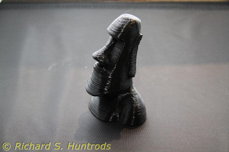
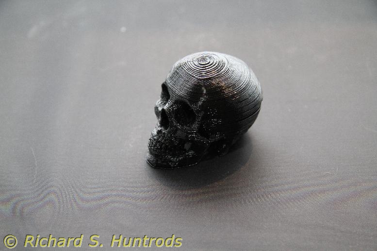
In the meantime, I’ve now printed several ‘toys’, including several cubes, an easter island head and a small skull, plus a toy soldier for a game that seems popular.
For more interesting projects, a few weeks ago I printed a ball mount for my SOLA 1200 video light that works very well. Last week I printed a quick connect ball mount for my underwater housing. It was two parts, and there were undercuts that didn’t print properly, but it does fit and work. I bought some cyanoacrylate glue (Loctite 420) which works very well gluing close facing items.
Finally, after much testing and frustration, I found one gear that would work in my other underwater housing as a focus gear. It needed scaling (120% x & y) and also additional cylinders to fit the lens. After trying many things, I bit the bullet and tried designing it myself using TinkerCad. TinkerCad is from Autodesk and is a 100% on-line browser based tool. It was easy to get working and took little time to design my set of cylinders to fit the gear. Trial #1 broke (too thin on the upper cylinder) and the gear was too thick. I redesigned the cylinders and re-scaled the gear, and after gluing it works and fits perfectly.
Later I designed the same cylinder set in Autodesk’s Fusion 360, which is a bit more complex a program than TinkerCad, but resides on my PC which I prefer.
All in all a productive and fun week with the printer.
3D Printer – now better
As I mentioned in the last blog post, I printed a new z-endstop for the printer to replace the one zip-tied in place. The problem with the zip tie stop was the zip tie was on a smooth rod, and it would move if bumped by the carriage.
The first one I printed looked pretty nice; it mounted on one z-axis motor and was designed to hold the microswitch up to contact a printed adjustment piece. The problem with this type was first the mount holes were totally wrong for the style of microswitch I had (too close) and the triangular shape of the holder prevented proper holes from being drilled. The adjuster also would not fit on my x axis motor, so the whole thing was a dud.
I kept looking and finally found a printable small triangular mount that was easy to print, and captures the microswitch perfectly. It takes up almost no room. I had to print this one using a cobbled together solution as I’d removed the zip-tied endstop trying to get the first printed one to work. The printing was not great (the holes were not centered properly) but I was able to drill it and once installed it works perfectly.
Since then I’ve printed a few things, and had a few failures due to my newness at 3d printing, but it’s all good and fun again.
3D Printer – It’s dead, Jim… no wait! IT’S ALIVE!!! (and a lesson)
Yea, I know. Really, really cheezy title. Tough.
Last week I went to make a print for my underwater video light – a quick disconnect ball mount so I can leave the ball mount permanently attached to the video light no matter what housing I use. It looked pretty straightforward, and I started to print…
… only to find it was pooping it’s thread from about 5mm instead of onto the bed. I checked and confirmed the height was off, so corrected it. It did it again! I tested the x-axis extruder height, and it was also off level. This was very strange as nothing had changed, but as I was checking I discovered the z axis was moving when I touched it. It is NOT supposed to do that.
More checking confirmed the bad news – one of the nuts that is part of the z axis was totally stripped. You could take the threaded rod and zip it back and forth holding the nut. The other nut was OK, but for now the printer was down.
A detailed analysis plus a bit of an “aha” moment involving the same threaded rod and the video light made me realize the so-called 5mm threaded rod was actually a 10-32 imperial thread. It was not metric at all. I have 10-32 nuts, bought as part of the video light project, and they fit perfectly on the threaded rod. More interestingly, the 5mm nuts showed significant “lash” on the rod while the 10-32 nuts showed almost none.
The only problem was the 10-32 nuts were too large to mount on the printer. I tried epoxy, but it just peeled off the PLA mount once cured. All the fancy stores were closed Saturday, including one that was supposed to be open but could not bother to post that on the website or make an answering machine message, so I was out of luck until today.
This morning I went to Fastenal in Nanaimo, looking for “threaded rivets” a.k.a. rivet nuts. These are marvelous threaded tubes about .5 in long by whatever thread you want. They would solve the problem perfectly. Unfortunately, they were out of stock and it would be a week for more. However, they did have true 5mm stainless threaded rod and stainless 5mm nuts. I bought both, came home and cut the rod to length and installed it. With the new nuts, it was back to a working printer in a matter of about an hour.
Once rebuild, I had to level the x axis again. The height is controlled by the two z axis threaded rods, and though you can get really close by evening the nuts before you assemble it, it’s best to fine tune with a strip of paper and the extruder.
The first print was again the 20mm cube, as that’s a really good test of the printer and allows me to verify all dimensions. It turned out the z face was high – 20.05mm and not 20mm, so I grabbed the internet and checked thread pitches. It turns out they are most certainly NOT the same. 10-32 is 32 tpi (thread per inch), or 0.03125 / inch. Metric 5mm is usually 0.8mm pitch, which is 0.03150. It seems so close, but when dealing with 0.1 mm it’s not close enough. The 0.8mm pitch is just a tad coarser – equivalent to 31.75tpi. I adjusted the firmware print constant to account for the difference, and the second 20mm cube was exactly 20mm as it should be.
Now I’m printing a new z-endstop for the printer. The current z endstop is just zip tied in place, and it would move while I was leveling the x axis. This is not good, so I found some printable ones and will see what I can devise.
At least the printer is again functional, which is a great relief to me.
More 3D Printing
I’m reflecting on the 3D printer and how it’s been working for me, and overall I’m very happy. For something I build from plans but with a lot of my own design, it’s working very well.
Some notes so far:
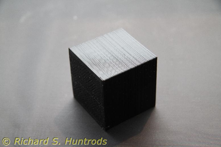
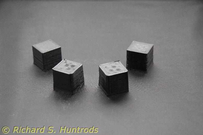
- I used a caliper to measure my cubes. They are, in fact, exactly 20mm on every face. They did not shrink. That’s great news.
- slic3r is a great program. In addition to letting you preview layers, it has scaling features. Using those I scaled the 20mm cube by 200% today and thus printed a perfect 40mm cube (confirmed by the calipers).
- The blue tape is an excellent bed for PLA prints
- There are a lot of available things to print on the internet, but now it’s time to learn blender and make some of my own. There are things I want to print that no-one else has designed yet, so now it’s my turn. 🙂
Today I’m printing a lens gear for the Canon DLSR. I doubt it will fit in the underwater housing (or interlock with the control wheel if it does, but it’s a start and I can then work with designs to create my own focus and/or zoom gears down the road.